This standard applies to drainage continuous casting, centrifugal casting and sand casting of gray cast iron straight pipe (hereinafter referred to as drainage straight pipe) and gray cast iron pipe fittings (hereinafter referred to as drainage pipe fittings).
The use of straight drainage pipes and fittings should refer to the relevant pipeline design and construction specifications.
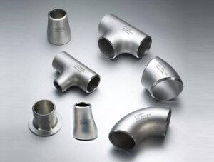
1 Type
Drainage straight pipe and fittings are used socket type, according to the shape of the pipe socket part A type and B type.
2 Size, shape, weight
2.1 Size, external shape and weight
2.1.1 A-type drainage straight pipe shape, size and weight should be consistent with the provisions of Figure 1 (omitted), Table 1 (omitted) and Table 3 (omitted).
The shape, size and weight of the B-type drainage straight pipe shall conform to the provisions of Figure 1 (omitted), Table 2 (omitted) and Table 3 (omitted).
2.1.2 The fixed length of the drainage straight pipe shall comply with the provisions of Table 3 (omitted). If different lengths of straight drainage pipes are required, the production can be negotiated between the supply and demand sides.
2.1.3 The name and graphic marking of drainage pipe parts should comply with the provisions of Table 4 (omitted).
2.1.4 The shape, size and weight of the drainage pipe parts shall conform to the provisions of Figure 2 (omitted) ~ 12 (omitted) and Table 9 (omitted) ~ 19 (omitted).
2.2 Shape
2.2.1 The curvature of the straight drainage pipe should comply with the provisions of Table 5.
Table 5
Nominal caliber Dg, mm bending degree, mm / m
50~100 ≤4
125 ~ 200 ≤ 3
2.2.2 Drainage straight pipe end face and pipe fitting end face should be perpendicular to the axis.
2.2.3 Allowable deviation of the angle of the two axes of drainage pipe fittings is ±1°30′.
2.3 Dimensional deviation
2.3.1 Socket outer diameter, socket inner diameter and socket depth deviation
The allowable deviation of socket outer diameter, socket inner diameter and socket depth of straight drainage pipe and pipe fittings shall conform to the provisions of Table 6.
Table 6 mm
Nominal diameter Dg, mm Socket outer diameter Socket inner diameter Socket depth
50~100 +1.0
-1.5 +1.5
-1.0 ±2.0
125~200 +1.5
-2.0 +2.0
-1.5 ±3.0
2.3.2 Wall thickness deviation
The allowable deviation of wall thickness of straight drainage pipes and fittings shall conform to the provisions of Table 7.
Table 7 mm
Nominal diameter Dg, mm Wall thickness
50 ~ 100 ± 0.7
125 ~ 200 ±1.0
2.3.3 Length deviation
Allowable deviation of drainage straight pipe length should be in accordance with the provisions of Table 8.
Table 8 mm
Nominal caliber Dg, mm Wall thickness
50 ~ 1000 ±5.0
1500 ~ 2000 ±8.0
Allowable deviation of the length of the axis of the drainage pipe parts is ±3mm.
2.4 Weight and its deviation
Drainage straight and mound fittings are delivered by theoretical weight.
The allowable negative deviation of the weight of each drainage straight pipe is 8%.
The allowable negative deviation of the weight of each drainage pipe fitting is 10%.
3 Technical requirements
3.1 Chemical composition
The phosphorus content of straight drainage pipes and fittings should be no more than 0.30%, and the sulfur content should be no more than 0.10%.
3.2 Mechanical properties
The tensile strength of drainage pipes and fittings should be not less than 140N/mm2 (14kgf/mm2).
3.3 Process performance
Drainage straight pipe should be hydraulic test, the test pressure of 1.47MPa (1-5kgf/mm2), the hydraulic test of pipe fittings by the supply and demand side consultation.
3.4 Organization
Drainage pipes and pipe fittings should be gray cast iron, the organization should be dense and easy to cut.
3.5 Surface quality
Drainage straight pipe and pipe fittings inside and outside the surface must be bright and clean, does not allow cracks, cold partition, misalignment, honeycomb and any other obvious defects that prevent the use of.
Casting defects that do not affect the use are allowed to repair or exist, but the local raised areas must be ground flat after repair.
3.6 Coating
3.6.1 Drainage straight pipe and pipe fittings inside and outside the surface can be coated with asphaltene or other anti-corrosion
3.6.2 The inner and outer surfaces should be clean and free of rust and iron flakes before coating. After coating, the coating should be uniform and firmly adhered, and there should be no obvious accumulation.
4 Test method
4.1 Drainage straight and mound pipe fittings size with calipers or sample plate and its gauges with sufficient accuracy for measurement.
4.2 Drainage straight and pipe fittings surface quality and coating quality with the naked eye for inspection.
4.3 Chemical analysis according to GB 223.1 ~ 223.8-81, GB 223.9 ~ 223.24-82 “Steel and alloy chemical analysis methods” of the relevant provisions.
4.4 tensile test according to GB 228-87 “Metal Tensile Test Methods” provisions.
The use of metal type casting of the tensile test bar in the metal type neutral casting into.
The use of sand casting tensile test bar in the same type of sand cast in the neutral casting.
4.5 Hydraulic test must be carried out before coating, when up to the prescribed pressure, steady pressure of not less than 10s, the tube should be no leakage.
5 Inspection rules
5.1 Inspection and acceptance
Inspection and acceptance of straight drainage pipes and pipe fittings are carried out by the technical quality supervision department of the supplier.
5.2 Group batch rules
5.2.1 Continuous casting and centrifugal casting of non-water straight pipe should be inspected and accepted by batch. Each batch shall be composed of drainage straight pipes of the same nominal diameter, the same wall thickness, the same fixed length and the same chemical analysis results.
5.2.2 Drainage pipes and fittings of sand casting shall be inspected and accepted by batch. Each batch should be composed of the same molding process and the same chemical analysis results of drainage pipes and pipe fittings.
5.3 Sampling quantity
5.3.1 The surface quality and coating quality of drainage pipes and fittings should be checked root by root.
5.3.2 Chemical analysis of each shift (8h) to take two samples, when the furnace material change must be chemical analysis. The test results represent all the drainage straight pipes and fittings produced on that shift.
5.3.3 Tensile test: take two specimens per shift (8h). The test results represent all the drainage pipes and fittings produced on the shift.
5.3.4 Drainage straight pipe should be hydraulic test by root.
5.4 Retesting and discriminatory rules
When the chemical composition, tensile test results in any one of the test failed