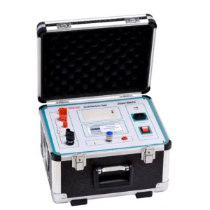
Why are loop resistance tests needed?
Planes are struck by lightning about once a year*, based on data from the US Federal Aviation Authority (FAA). That’s surprisingly often isn’t it? It happens much more frequently than most people would assume.
The good news is that standard aircraft are designed to handle lightning strikes. A low resistance path is built into the design, enabling the lightning current to flow from the point of impact through to the tail of the plane where it can safely exit.
So, the principle behind the design is simple enough. However, a single high resistance joint can hinder the route of the lightning current, possibly resulting in catastrophe.
What can go wrong with a high-resistance joint?
Correct electrical bonding is critical in ensuring the safety of aircraft and passengers. As already mentioned, a single high-resistance joint is all it takes to render a lightning strike protection circuit useless.
Worse than that, the high-resistance joint becomes the focus of up to 200kA of lightning current trying to escape, which can lead to catastrophe.
High-resistance bonds can be caused by of the following reasons – and there are many more:
- Surface contamination
- Bonding surfaces being incorrectly prepared
- Missing components
- Faulty materials
- Loose crimps
- Loose ring terminals
- Incorrectly rated bonding straps
Aircraft are intricate mechanical and electrical assemblies; there are thousands of bonding points and ground circuits which need to be tested to ensure a low resistance path. A loop resistance test is therefore essential, but it can be time consuming and complex.
What is tested during a loop resistance test?
The various elements that combine to provide a low resistance path for the lightning strike to follow are called a bonding circuit. These elements are a combination of aerostructure sections, flight equipment housings/casing, cable harness shields, piping systems and bond straps.
It is the complexity of these elements that makes the efficacy of the testing method and validation of test results so important.
What’s the best bond and loop resistance test method?
Simple electrical bonds between two separate elements are relatively straightforward to test. Applying the Kelvin measurement principle, bond meters will cause a current to flow between the two elements, measure the volt drop across the bond, and report the resistance.
Is the Kelvin measurement principle appropriate for all circuits?
This method is not suitable when it comes to testing circuits containing parallel paths; despite this, bond meters are still frequently – and incorrectly – used in this scenario.
To explain why this is, take the below illustration (figure 1) as an example. The two sections of aircraft structure are connected by a series of bonding straps; one of the bonding points has been badly assembled and is an open circuit.
